The third part
1 standard tolerances and deviations
In order to facilitate the production, to achieve the interchangeable parts and meet the different requirements of the use of the national standard "limits and cooperation", the tolerance zone is composed of two elements, the standard tolerance and the basic deviation. The tolerance zone is defined by the standard tolerance, and the position of the tolerance zone is determined by the basic deviation.
(1) standard tolerance (IT)
The value of the standard tolerance is determined by the base size and tolerance level. The tolerance level is the mark of the precise degree of the size. Standard tolerance is divided into 20, that is, IT01, IT0, IT1, … IT18. Its size accuracy from IT01 to IT18 in order to reduce. The specific values of the standard tolerances are met in the relevant standards.
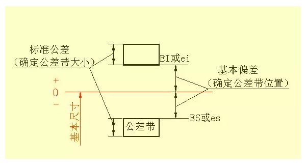
(2) basic deviation
Basic deviation is defined in the standard limit and fit, to determine the relative position of the deviation of the relative position of the deviation or under deviation, generally refers to the deviation near the zero line. When the tolerance band at the top of the zero line, the basic deviation for the next deviation; otherwise, it is on the deviation. The basic deviation of a total of 28, numerical control WeChat cncdar code with the Latin alphabet, capital for the hole, the lower case for the axis. From a series of basic deviation can be seen from the figure that the basic hole deviation of A ~ H and K ~ ZC basic axis deviation for the deviation; the basic deviation of a hole, the basic deviation of K ~ ZC and a ~ H axis deviation, JS and JS of the tolerance zone are distributed symmetrically on the zero line both sides of the hole and shaft the upper and lower deviation respectively are +IT/2 and -IT/2. The basic deviation series is only the position of the tolerance zone, not the size of the tolerance, therefore, the tolerance zone is the opening, the other end of the opening is defined by the standard tolerance.

The basic deviation and standard tolerance, according to the definition of dimensional tolerance, there are the following calculation formula:
ES=EI+IT or EI=ES-IT
Ei=es-IT or es=ei+IT
Hole and shaft tolerance zone code with basic deviation code and tolerance zone grade code composition.
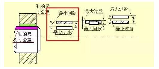
A, fit
The relationship between the basic dimensions of the same, the mutual binding of the hole and the shaft tolerance zone is known as the fit. According to the different requirements of the use, the hole and the shaft with loose tight, and thus the national standard with the type:
1) clearance fit
Hole and shaft assembly, there is a gap (including the minimum gap is equal to zero). The tolerance of the hole is above the tolerance zone of the shaft.
2) transition fit
Hole and shaft assembly, there may be clearance or interference fit. Tolerance zone of the hole and the tolerance zone of the shaft are overlapped with each other.
3) interference fit
Hole and shaft assembly has a surplus (including the smallest interference is equal to zero). The tolerance of the hole is under the tolerance zone of the shaft.
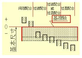
B, benchmark system:
In the manufacture of mating parts, in which a part as a benchmark, it must have basic deviation, by changing another basic deviation of non reference parts to obtain different properties with the system is called the reference system. According to the actual needs of production, the national standard provides two benchmark system.
(1) base hole system (as shown below)
The basic hole system is a kind of system, which is a kind of system which is formed by the basic deviation of the tolerance zone of the hole with different basic deviation. See left below. The base hole is called the datum hole, its basic deviation code is H, its next deviation is zero.
(2) based on the axis system (as shown in the figure below)
Basic shaft system is a kind of system, which is a kind of system which is formed by the basic deviation of the tolerance zone of the shaft with different basic deviation. See right below. The axis of the base axis is called the datum axis, its basic deviation code is h, its upper deviation is zero.
C, with code
With the code from the hole and the axis of the tolerance zone code, written in the form of fraction with molecular code hole tolerance, the denominator is the axis of the tolerance zone code. With WeChat H CNC cncdar all in the molecule basic hole system with all the denominator containing H based axis system with.
For example, φ 25H7/g6 refers to the coordination of basic dimensions of φ the gap between the 25, the basic hole system with reference hole tolerance zone is H7, (the basic deviation of H tolerance level 7), the axis of the tolerance zone is G6 (the basic error is g, the tolerance level 6).
For example, φ 25N7/h6 refers to the coordination of basic dimensions of φ 25, the axis system transition fit, reference axis tolerances of H6 (basic deviation of H, tolerance level 6), hole tolerance zone is N7 (the basic error is N, the tolerance level 7).
Marking of tolerances and fits on patterns
1) on the assembly drawing, the tolerance and cooperation are marked.
2) there are three forms of marking on parts drawing.

2 form and position tolerance
Parts processing, not only the size of the error, but also the geometric shape and the location of the error. Cylinder, even in the size of qualified, there may be one end of the large, small or middle of the other end of the middle and small ends of the rough and other situations, the cross section also may not be round, which belongs to the shape of the error. Stepped shaft, the processing may appear in the different axis of the axis of the situation, which belongs to the location of the error. So, the shape tolerance is the allowable variation of the shape of the ideal shape. Position tolerance is the allowable variation of the ideal position in the actual position. Abbreviated form and position tolerance.

Symbol for form and position tolerance items
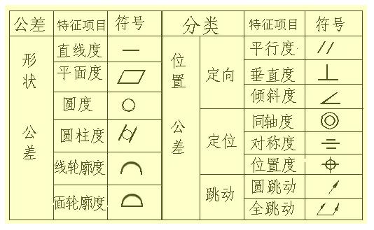
1) code for shape and position tolerances
The national standard 1182-1996 GB/T provides for the use of symbols to label shapes andPosition tolerance. In actual production, when the code is not allowed to be used to mark the form and position tolerance, it is allowed to be used in the technical requirements. Form position tolerance includes various items of form and position tolerance symbols, geometric tolerance and lead frame to form and position tolerances, numerical and other relevant symbols, and reference code etc.. Box font height h and pattern size digital high.

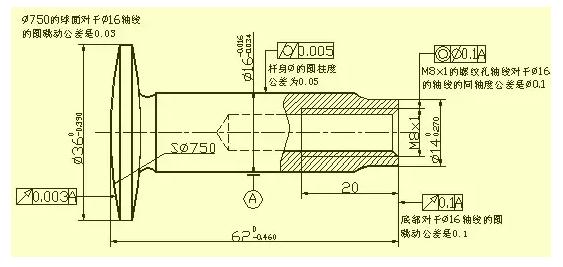
2) form and position tolerance annotation example
A valve stem, in the map marked by the shape and position tolerance in the vicinity of the added text, just to give the reader a note and repeat it, in the actual pattern does not need to repeat.
The fourth part
Casting structure on 1 parts
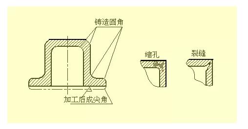
(1) cast fillet
When the parts of the blank for the casting, due to the requirements of the casting process, the surface of the intersection of the corner of the casting should be made into the corner. The casting round corner can prevent the sand falling phenomenon at the corner of the casting and the shrinkage and crack when the metal is cooled. Cast round the size of the general to take R=3~5mm, in the technical requirements of the uniform.
(2) model angle
Manufacturing blank with casting method, in order to facilitate the sand out of shape, generally along the direction of pull for about 1 appearance: 20 slope, called the draft. Therefore, there is a corresponding draft in the casting, the slope can not marked on the map, not necessarily draw, as shown below; when necessary, can be explained by the text in the technical requirement.
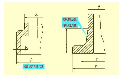
(3) the thickness of the casting
When the wall thickness of the casting is not uniform, the casting is casting, because the metal cooling speed is different, the crack and shrinkage phenomenon will be produced. As a result, the wall thickness of the casting should be as uniform as possible, see the image above. When the connection of different wall thickness must be used, the gradual transition should be adopted. Wall thickness of casting is usually directly outjection.
Mechanical processing structure on 2 parts
(1) cutting tool and grinding wheel
When machining parts, in order to facilitate the withdrawal of the tool and to ensure the assembly of the relevant parts of the contact surface by tight, in the process of surface steps should be processed in advance of the cutter groove or grinding wheel. Turning the outer circle of the back of the knife slot, numerical control WeChat cncdar its size can generally be " groove width × diameter " or " groove width × groove depth " way tagging. The grinding wheel grinding circle and the outer circle and the undercut.
(2) drilling structure
With the blind hole drill out, there is a 120° at the bottom; the cone angle, drilling depth refers to the depth of the cylindrical part, not including the cone pit. In the transition of stepped hole, there is a round table, the cone angle of 120° drawing and dimensioning.

When the drill bit is used, the drill head is required to be perpendicular to the end face of the drilled hole so as to ensure that the drill hole is accurate and avoids the drill bit broken. Correct structure of three kinds of end face of drill holes.
(3) convex and concave
Parts and other parts of the contact surface, the general need to process. In order to reduce the processing area, and ensure that the parts have good contact between the surface, often in the design of the casting on the convex, concave. In order to reduce the processing area, the groove structure is made in order to reduce the processing area.

 苏公网安备 32011402010684号 |
苏ICP备15029307号-1
苏公网安备 32011402010684号 |
苏ICP备15029307号-1

