Process flow chart is a key document for process design, as well as a guiding tool in the process of production. What is said here is only used in production practice, we should understand the basic knowledge (related to the content of the chemical process design content is interested in the peer can find some information). It takes the image of graphics, symbols and codes, represent the process selection of chemical equipment, piping, fittings and instruments such as arrangement and connection, so as to express a change in the chemical production process of matter and energy. Flow chart is the basis of the design of piping, instrumentation, equipment design and installation. It is also a guide for operation and maintenance.
In production practice, we often can see the process of expression of the process drawings generally only two kinds, that is, we know that PFD and P& ID. PFD is actually English word prefix abbreviation, called Process Flow Diagram, a Chinese on translation is “ process flow diagram of ” meaning. P& ID is English word prefix abbreviation, called the Piping and Instrumentation Diagram, “ & ” and said in english. Sentence translation is “ process piping and instrumentation diagrams ”. The main difference between the two is that the number of the contents of the figure is different, PFD is more than P& ID content is simple. A more clear explanation is P& ID drawings basically includes a scene in all of the pipe fittings, valves, instrumentation and control points, very comprehensive, while PFD will map the entire production process can be explicitly stated, not all valves, pipe fittings, instruments are drawn.
In addition, there is a kind of drawing is not a process, but it is also very important that the equipment layout. But relative to the above two class diagram, it is much easier to read, so just do a brief introduction.
Here are some of the drawings we often see some of the content and representation.
First, the main contents of the flow chart
No matter what kind, what kind of flow chart, summed up the contents includes graphics, labels, etc. the column heading legend, the four part, we got a drawing, the first is the overall understanding about its main content. The specific contents are as follows:
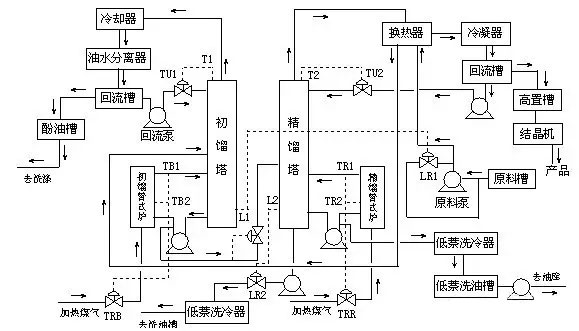
1, graphics
All process equipment in a simple form on the same plane, and then coupled with the main, auxiliary pipeline and pipe fittings, valves, instrumentation control points, etc..
2, tagging
Main note and write equipment number and name, pipe segment number, control point code, the necessary size data, etc..
3, legend
Code, symbols and other marking instructions.
4, title bar
Write design stage name, drawing number, etc..
The four main components of the drawings, we can understand each specific content of each part of the reading process construction flow chart, first understand the title bar and legend, master name, read drawing from a variety of graphic symbols and codes and the significance of line labeling; then based on mastering equipment the name and code number, on the understanding of the main material flow line, in the direction of the arrow to find the one by one through the device, the control point and the resultant of each equipment and materials after the final discharge; finally understand the other flow line, such as steam, condensate and water lines and water pipelines etc..
Two, flow chart of the device representation
The equipment on the flow chart is marked with the number and the name of the device, and the number of equipment is marked in two places. The first is above or below the map, requestorder, and as far as possible is below the line in equipment, marking equipment name is second; or in the vicinity of the device, here only note number, note. When several devices or machines are vertically arranged, their number and name can be marked in the order of the upper and lower.
Weave process equipment, is this: each process equipment shall be compiled in a number, flow chart, equipment layout and piping layout marked number, in number below to draw a solid line, which, as shown below:
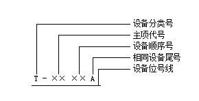
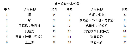
The main item of the code is generally composed of two digits, the previous digital display device (or workshop) code. After a number to indicate the main item code, in general engineering design, only the main item can be. A device or workshop code and main code designed by the total charge given in the work report; equipment with two digit sequence number 01, 02, 10, and … … representation; the same equipment tail number for the same equipment from a number, with the letters A, B, English, & C hellip; … tail number representation. Commonly used equipment classification code to see the next table, the general use of the English name of the first letter of the equipment.
Three, flow chart in the representation of the pipeline
Process piping marked with combination, pipeline, pipe combination, is composed of four parts, namely, the pipeline (or pipe segment, composed of three units), pipe diameter, pipe grade or sound insulation and heat insulation. Were divided into three groups, separated by a hyphen to groups, separated between the two groups with the appropriate gap, combination of General mark above the pipeline, as shown in figure:
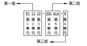
The first group has three units, which are the material code, the main item number and the pipeline sequence number. One of the first units for the material code, by the 1~3 of the English alphabet, a variety of material code table, the table is not specified in the code of the material by the professional technical personnel in alphabetical.

The second unit is the main item number, fill in the item number according to the main provisions of the project, with two digits, from 01, 02 to 99; the third unit for the pipeline sequence number, the same kind of material in the same subject in order to flow, order number. Using two digits, starting from 01, 02, to 99 so far. The first group consists of three units (Guan Duanhao).
The second group consists of fifth, two and fourth units, and the fourth unit is the tube.Road dimensions, nominal diameter, nominal. Take the mm as the unit, but only the note number, does not pay attention to the unit; the fifth unit is the pipeline grade by three parts, see figure below:
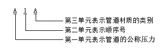
The first part of the nominal pressure pipe (MPa) grade, said English uppercase letters, A~K standard for ANSI (pressure grade code including I, J, L~Z is not used) for domestic standard pressure level code (O, X). Refer to the following table for the specific meaning of pipe pressure rating code:

The second part is the sequence number, represented by the Arabia figures, by the beginning of 1; the third part is the pipe material category, represented by uppercase letters English, its meaning is as follows: A— iron; B— C— ordinary carbon steel; low alloy steels; alloy steel; D— E— F— stainless steel; non ferrous metals; G&mdash H—; non metals; lining and coating.
The third group consists of sixth units, which is the code for heat insulation and sound insulation:
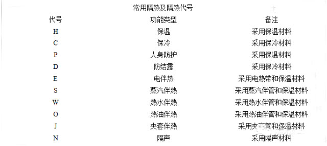
When the technological process is simple, the pipeline varieties specifications are not long, the number of pipeline combination of fifth, two 6 units can be omitted. Fourth the size of the unit can be directly filled in the outer diameter of the pipe × wall thickness, and marked the engineering requirements of the pipe material code.
Four, valve and pipe fitting method
All kinds of valves and piping accessories, such as the flow chart of compensator, hose, permanent (temporary) water funnel and non-standard fittings are in the legend of out filter, blind, trap, mirror, flame arrester, reducers, and so in the part of reading reference legend can read drawings very well the.
Five, instrument control and analysis of sampling point representation
Process flow chart is marked out of all the process related to the detection of instrumentation, control systems, analysis of sampling points and sampling valve. Its symbol, code, see table below:

Instrument control symbols point draw fine line for general use, graphics, symbols of various actuators and valve symbols can also be found in the legend. Combined instrument graphic symbols and letters code, can be said to be measured variables and functions of industrial instrumentation process, or the name of that instrument, equipment, components and pipelines; and Arabia letter number combination, is composed of a number of instruments.
In the detection and control system, each meter or element in a loop should be marked with the instrument position. The instrument position is composed of the letter combination and the Arabia digit number. The first letter indicates the variable, and the following letter indicates the function of the instrument. Number expressed sequence number of instruments, numbers can be edited according to the workshop or section, as shown below.

Six, equipment layout
The equipment, piping and control points identified in the process flow chart shall be reasonably arranged and installed according to the technological requirements. The expression of a workshop or a section of the equipment to the inside and outside in the workshop layout and installation drawings, called equipment layout. Building plans are drawn in the view of the principle of the positive projection. It includes elevation, profile and plan, etc., commonly used in the construction plans and more for the plant plan and profile.
Standard in Architectural Drawing: walls, columns, building the walls, with dotted lines draw their positioning and axis number. The vertical axis positioning plan, according to the horizontal direction from left to right in Arabia number, horizontal axis positioning, is vertical to the direction from the bottom to the top with a capital letter pull huan. In elevation and section, can only draw the most lateral wall or column of the axis and number.
The relative height of a part of a plant, called &ldquo, is ”. Elevation value in meters as a unit, the general note to the decimal point after the third. General to the first floor elevation for zero elevation, injection into ± 0, zero elevation above positive elevation, without a positive elevation value; zero elevation following negative elevation, negative elevation before writing a.
 苏公网安备 32011402010684号 |
苏ICP备15029307号-1
苏公网安备 32011402010684号 |
苏ICP备15029307号-1

