[introduction] piping and instrument diagram is an important part of chemical process design. In the design process, should be based on the requirements of the process flow chart, in detail the system of all equipment, instrumentation, piping, valves and other relevant public works system. This paper mainly introduces the typical design examples of pressure, temperature, pump and container flow chart. I hope this article can help you to completely understand the tower, heat exchanger, air cooler, heating furnace, compressor, dust separator, jacket, sampling equipment, such as chemical industry, the design method of a variety of equipment.
Design of piping and instrument flow chart of heating furnace
1, design points
The import and export pipeline should be symmetrical heating furnace material (especially in gas-liquid two-phase flow, the instrument can not measure, the valve can not be adjusted), the pressure loss and should not be large, supervisor must have enough section.
To make uniform flow distribution of pipe flow, non two-phase flow, in addition to the symmetrical arrangement, in each set, and branch line is arranged on the control valve and metering facilities (generally should be installed in the liquid feed pipe). In order to check the heating condition, temperature measuring instruments should be set on the outlet pipeline of the heating furnace, which can not consider the symmetrical arrangement of the pipe, and the temperature of the material is adjusted and controlled by the valve.
The heating furnace steam vent pipe should be set on the muffler.
The need to inject water or steam in the furnace tube, should be in the pipeline into the water and steam line set shut-off valve and check valve, check valve and a two valve in the middle, lest material poured into the water or steam system.
The valve should be installed in the entrance pipeline heating furnace, the minimum foot inch DN50; in the export pipeline shall be provided on the net valve.
In the convection section and the radiation section of the furnace, usually equipped with fire extinguishing steam joints DN50. When the rupture of the furnace tube, the fire extinguishing steam valve can be opened, so that the steam enters into the furnace to extinguish fire. The large heating furnace may be equipped with a number of steam fire extinguishers. Fire extinguishing steam is generally led by fresh steam pipe line. Because the pipe used only in the event of an accident of steam fire, so from the shut-off valve to the pipeline heating furnace without insulation, without pressure test, can be larger than the general pipeline span, height without emptying valve, the lower drill hole discharge condensate Φ 6.
2, typical design examples

Fig. four symmetrical duct arrangement of the feeding of heating furnace 1
Fig. four the symmetrical duct arrangement of the heating furnace for 1 way feed. Symmetric part of the pipe length diameter, the number and form of valves and pipe fittings must be the same.
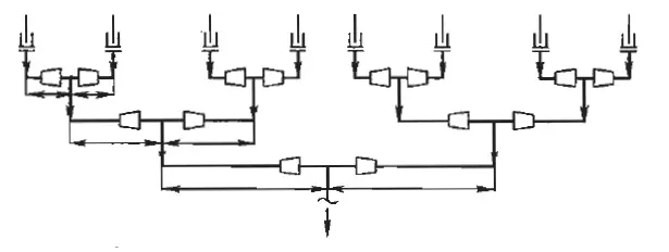
Fig. eight symmetrical duct arrangement of the heating furnace 2 and flow into the material
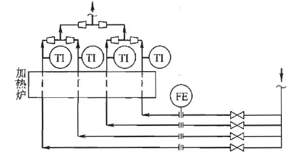
Fig. four layout of feeding pipe of heating furnace 3
Figure 14 shows the 3 way feeding of the heating furnace material piping layout. The flow rate of each road is controlled by a stop valve before the furnace inlet and a metering orifice plate is provided. At run time, to ensure that the flow of each furnace tube is the same, that is, the outlet temperature of each furnace tube is the same.
Two, the compressor pipeline and instrument flow chart design
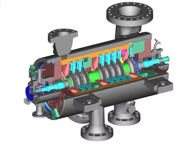
Compressor according to its working principle can be divided into two types of volume type and speed type. Piston type, screw type and water ring type are usually used in the volume type compressor, and the centrifugal type and axial flow type are usually used for the speed type compressor. The compressor is driven by electric and steam turbines.
1, design points
The inlet and outlet pipes of the compressor should be set to cut off valve. The inlet pipe of the air suction type compressor is not cut off valve.
Filter between the compressor inlet pipe and the cut-off valve.
A buffer tank should be set for the suction inlet and outlet of the reciprocating compressor.
The compressor inlet section should be set before the condensate liquid separation tank.
The steam turbine compressor driven by steam turbine, the steam entrance pipe is provided with shut-off valve and filter.
The turbine shell bottom should set up trap continuous drainage.
The steam turbine exhaust steam pipeline with shut-off valve. Drainage facilities should be provided for the low point of the steam supply and exhaust steam pipe.
The exhaust pipe of the steam turbine should set safety valve, safety valve in the condenser. If the lack of steam pipe to enter the surface condenser installation of cut off valve, the safety valve should be set before the cut-off valve.
2, typical design examples
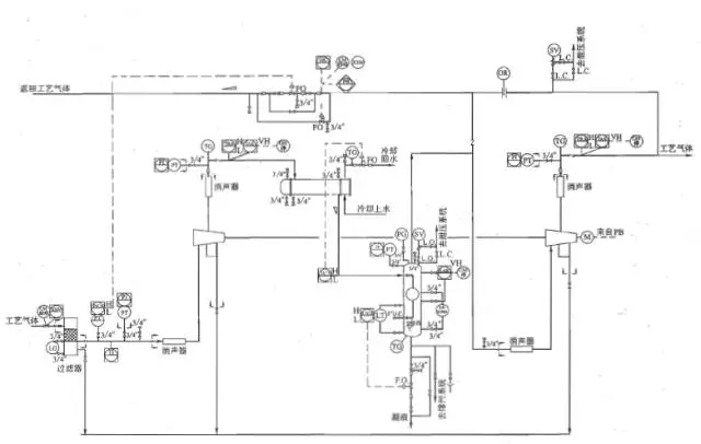
Fig. 4 flow chart of pipeline and instrument for compressor
Fig. 4 flow chart of piping and instruments for compressor. Inlet pipe of compressor is provided with cut off valve and filter. Each section of the import and export has a muffler, and at the same time, the temperature and pressure indicator. When the outlet temperature exceeds the specified value, the compressor emergency stop when the temperature exceeds the value of the interlock. A condenser and a liquid separating tank are arranged between the two sections. The liquid separating tank is provided with a safety valve, and the compressor can stop the compressor when the liquid level exceeds the interlocking value through the liquid level control drainage. Each outlet check valve. Two gas outlet of the compressor is provided with a safety valve, and the partial return to the compressor is adjusted according to the inlet pressure.
Three, dust separation equipment, piping and instrument flow chart design
Widely used in industry, the separation process is usually divided into dry process and wet process. Dry process dust removal equipment has gravity settling chamber, cyclone separator, bag filter, electrostatic precipitator, etc.. Wet dust removal device has a water bath dust collector, self-excited dust collector group, water film cyclone, foam dust collector, dust collector, Venturi Venturi and other multi washing tower scrubber. This section takes the bag filter and the washing tower as an example to illustrate the typical design of the flow chart of the pipeline and instrument.
1. Typical design of bag filter dust removal system
1) design points
The adjustment of the bag filter to control the amount of vent gas between the silo and the fluidized bed pressure, to ensure the smooth feeding hopper to the fluidized bed. According to the technical requirements, but also adjust the vent gas volume, gas pressure control silo or fluidized bed.
The pressure and pressure difference between the inlet and outlet of the bag filter can be detected, and the pressure value can be displayed in the local display or control room.
Purge the bag type filter by intermittent nitrogen gas. Nitrogen cut off valve can be in place, but also in the control room remote controlOpen and close.
The powder pipe between the bag filter and the hopper should be vertically laid, when some inevitable horizontal pipe, the horizontal pipe section should be designed for large angle inclined pipe smooth filtering.
In the dusty gas pipeline blockage, continuous purge with inert gas pipeline and rotor flowmeter, shut-off valve.
The long distance transportation of powder is arranged on the inert gas purge pipe and cut-off valve, to periodically purge.
The powder and dust gas pipeline installed on the ball valve, gate valve etc.; powder silo continuous feeding pipeline regularly to the fluidized bed, the automatic control of the feeding speed of the ball valve.
The silo operating under pressure, the safety valve plate is arranged on the top or blasting. If necessary, install the seal open shutoff valve in the pipeline between the equipment and the safety valve.
2 typical design examples
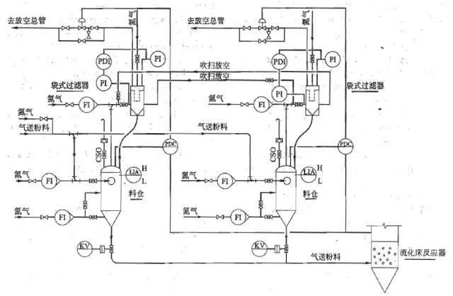
Fig. 5 basic unit model of bag filter dust removal system
Fig. 5 the flow chart of piping and instruments for bag filter dust removal system. Two sets of bag filter dust removal system, intermittent, intermittent cleaning. Powder conveying gas into the bunker, nitrogen several different parts in silo, silo powder and nitrogen into the fluidized bed reactor in the fluidized state. Gas transporting powder into the bag filter out from the top of silo, dust in the air is filtered to return hopper, the purified gas through the bag filter top vent.
Two sets of Bin - bag filter group alternately feeding - discharging operation. By the material and time gap material, cleaning operation by nitrogen blowback bag. A bag filter for purging, vent gas by purge vent pipe, vent by another bag filter after.
Bin - bag filter dust removal system for single equipment unit mode, basically the same as the example.
2, washing tower dust removal system
1) design points
In order to ensure the liquidity of the settling tank, the concentration of the slurry should be controlled in a certain range, which can not be too high.
To minimize dust gas and slurry pipeline resistance, the diameter is not little, take turns; bending radius is large, avoid sudden reducing etc..
When the washing column is pressed down, the pressure balance tube should be set between the gas phase and the settling tank of the tower.
The level of the slurry pipeline is longer, should be ≥ 0.005 slope, slope to the downstream equipment, and set the appropriate gas purge pipe.
When the fluid is pressurized by the nearby industrial water, and pipeline continuous supply, can be directly into the system; as for other media, should set up another fluid tank and pump.
In the raw gas inlet, a purifier tower and discharging slurry pipeline shall be set up the sampling point, analysis or set up online.
The tower according to need to set the safety valve. When you need to set the shut-off valve in the pipeline between the safety valve and the equipment when the shut-off valve should be opened with seals (CSO).
Between the washing tower and settling tank should have a certain difference, its value should be greater than the resistance between the tower and trough of 1 ~ 2m liquid column.
I do not use lotion circulation, settling tank is a slurry tank; when the washing tower still has enough volume, can also cancel the slurry tank, slurry discharge.
The washing tower purge control valve on the gas pipeline, according to need can also be with the upstream gas pressure regulating system of equipment. When the upstream equipment and the tower top pressure of the washing tower are not controlled by the control valve, the control valve group and the related facilities are cancelled.
Washing tower bottom discharge temperature is not high, do not need to discharge slurry cooling, cooler can be arranged on the outlet side of the fluid circulating pump.
Process needs washing tower purifying gas outlet side set up a special demisting device, separation layer washing tower can be cancelled.
Lotion and wash down from the gas phase powder as the downstream equipment continuous feeding, settling tank can be cancelled. In the slurry discharge pipe, according to the requirements of downstream equipment set flow control valve. The washing tower adopts fresh washing liquid, according to the operation requirements of the washing tower, a flow control valve or a washing tower kettle liquid level control valve is arranged on the liquid pipeline.
It is difficult to when the slurry pump, can be directly discharged or barrel (car) after sinotrans. Or take a slurry tank settling tank set with stirring noise, the slurry was suspended by slurry pump out under stirring.
2 typical design examples
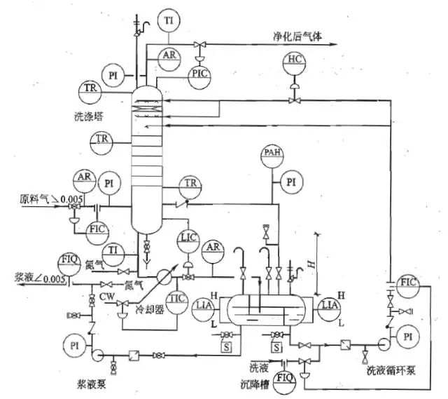
Fig. 6 basic unit model of dust removal system of washing tower
Fig. 6 flow chart of piping and instruments for the washing tower system. Dust containing gas from the bottom of the washing tower, full countercurrent contact down from the top spray lotion in the tower rises, and the dust removal of the washing. Gas purification after washing out from the top of the tower, or to vent downstream equipment. The washing liquid contains the dust from the gas, which is from the bottom of the tower. The settling tank is clarified and separated, and the washing tower is used for recycling. Fresh lotion in the pump before adding, containing the slurry pump from the slurry pump.
Four, with heat pipe, jacket and other accessories, such as the design of the annex
1, pipeline boundaries
The pipeline grade requirements by the pipeline material according to the process conditions and engineering, and strive to achieve the economic and reasonable principle to determine. In the project, only two pipe materials and the use of the nominal pressure of the pipe at the same time, marking the pipe level number is the same.
When there are different pipe connections, the process system should be specialized in the pipeline and instrument flow chart to mark different pipeline grades. Figure 7 represents a method for pipeline level division.
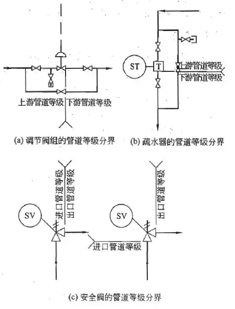
Method for the representation of pipeline level division 7
2, control valve group
Valve before and after the adjustment valve should be set. The selection of the control valve gas, gas off from the process of production safety to choose, in accordance with the process of determining the nature of the control scheme to determine the decision. In addition, but also consider the issue of regulating valve on the net. Permanent bypass valve for control valve group. For more than a certain size (usually 3”) with the hand wheel control valve, according to the process conditions, can not be bypassed.
3, two phase flow pipeline

A two - phase flow pipeline, such as an inlet pipe of an air cooler, can not be adjusted with a valve.Section flow. In order to distribute the flow evenly, the pipeline should be symmetrical.
4, lock and seal
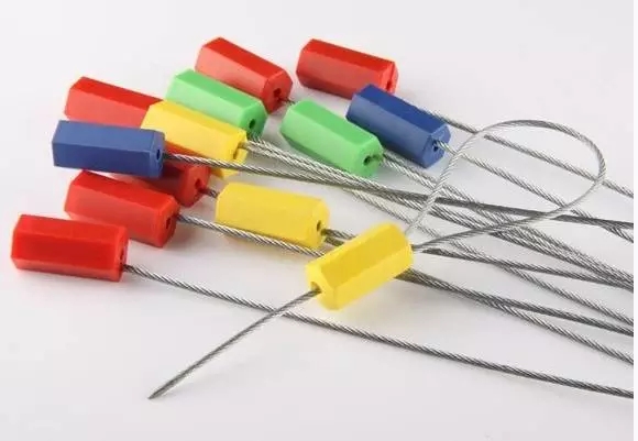
On weekdays do not need to open and close, is used only in the open parking or accident when the valve, in order to avoid misoperation, usually to lock or seal with lead seal. According to the general plan of opening and parking control valve, with lock; and when the valve is used to deal with the accident should be used to lead seal, so as to find the key and delay the timing of treatment of the accident.
5, thermal insulation
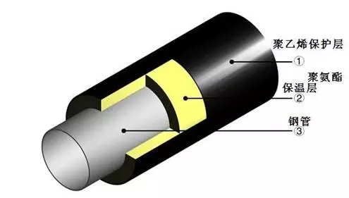
The insulation thickness of the pipe should be listed in the table can be in the pipeline, pipe segment piping and instrument diagram after the suffix that pipelines have insulation. When a pipe is not a whole heat preservation, piping and instrument flow diagram should be shown in the pipeline insulation range.
6, with heat
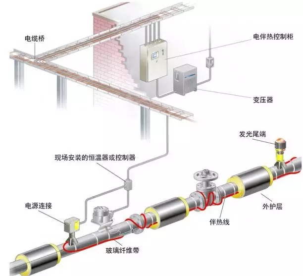
The heat tracing piping shall be listed on the piping list, and shall be accompanied by the heat range of the piping and instrument flow diagram.
7, jacket
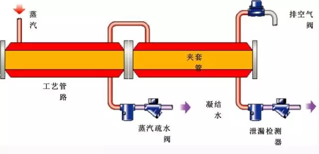
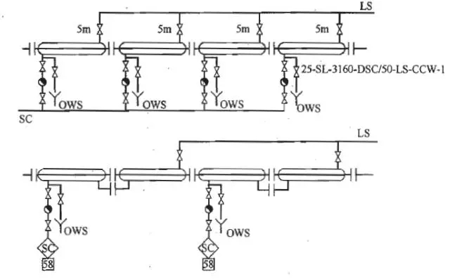
Figure 8 steam jacket (Note: need to specify each section of sleeve pipe length, diameter and diameter, and indicate the number of bars)
Figure 8 is the representation of the steam jacket in the pipeline and the flow chart of the instrument. Shown in the figure of jacket length, diameter, the diameter of the jacket and jacket of a number, showing the steam supply piping and steam condensate system.
8, sampling
1) sampling principle and method
The sampling point shall be drawn from the horizontal direction of the pipe side of the pipe or the pipe down 45° inclined out (liquid medium). The gas medium is usually upward 45° inclined extraction.
The vent pipe for a minimum of DN20 (3 / 4”), with the same size and interface devices connecting tube. In the face of corrosive fluids or in low temperature is the high viscosity fluid pipeline minimum DN25 (1”).
The process for the parser, the liquid pipeline (3/4” DN20), and the throttle valve of the same size (i.e., needle valve), gas (steam) pipeline is usually DN15 (1/2”), and the double flow valve (i.e. needle valve).
The upstream sampling point storage tank pipeline control valve should be located, and possibly located near the sewage pipeline.
The sample drawn from the high-temperature equipment pipe to set sampling cooler. Generally use stainless steel water cooling coil pipe cooler, the volume is not less than 0.1m3, the cooling area is not less than 0.25m2.
In the low temperature high viscosity fluid, need to purge pipe and cooler for steam or other media.
The type of the sample, as shown in Figure 9 to figure 17.
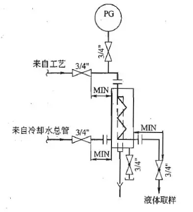
Fig. 9 cooling of condensate
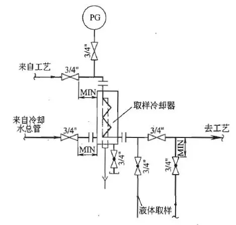
Fig. 10 sampling of hydrocarbon liquid cooling
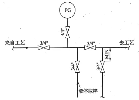
Fig. 11 sampling of hydrocarbon liquids
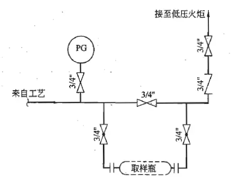
Fig. 12 hydrocarbon gas sampling
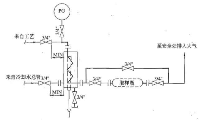
Fig. 13 cooling and sampling of gas (steam)
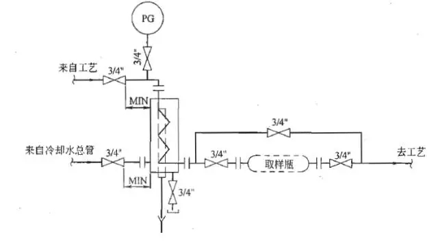
Fig. 14 sampling of hydrocarbon gas cooling
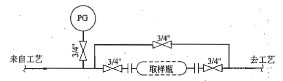
FIG. 15 general gas sampling

FIG. 16 sampling with purge
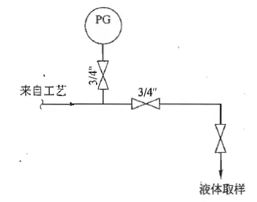
Fig. 17 general liquid sampling
2) selection of sampling valve
ANSI300#; a.&le with a single cut-off valve, the selection of the throttle valve or stop valve.
ANSI400#; b.&ge with a single cut-off valve or throttle valve, can also be used with a double gate valve.
C. steam hydrocarbon fluid pressure is not less than 0.45MPa, the double flow valve.
D. corrosive medium selection of single cut-off valve or throttle valve.
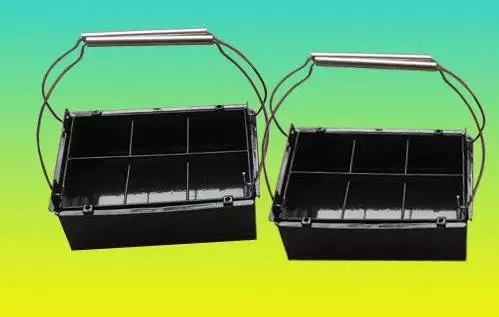
(3) sampling (personal protection) box
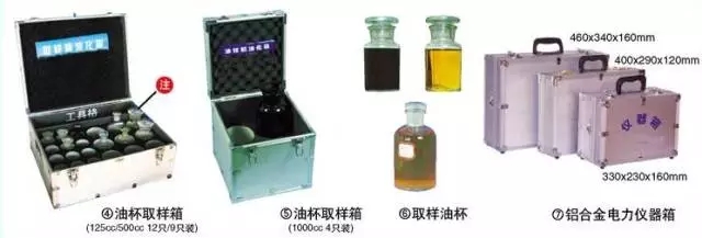
For the safety of hydrocarbon or corrosive medium, sampling is set in the sample box (namely the personal protective box), so that it can show the sampling point, and the small tube is not easy to be collided in order to ensure the safe sampling. Its shape and size of 400mm× 800mm× 1100mm (H) operating point from the floor for the 800mm, the total height of not less than 1900mm. The inside of the box can be provided with a cooler, a purge gas and a cooling water.
Process equipment network finishing release, reproduced please indicate the source.
 苏公网安备 32011402010684号 |
苏ICP备15029307号-1
苏公网安备 32011402010684号 |
苏ICP备15029307号-1

